Fournisseur professionnel chinois de moules de lentilles optiques & Inserts optiques & Moulage optique & Revêtement optique
Capacités Optiques Avancées



- Appelez-nous
+86 755 2308 9686 - Email de vente principal
sales@silveroptics.net - Whatsapp (en anglais seulement)
13530516428
Optical Injection Mold Design: Gate, Vent and Ejection Planning
September 15, 2026
For molded optical parts, the production tool is part of the optical system. Gate position, venting, cooling, ejection and insert design can influence flow marks, birefringence, warpage, surface replication and cycle stability. These decisions should be reviewed while the lens and housing interfaces are still adjustable.
Connect Mold Design to the Optical Requirement
The mold team needs more than a 3D solid. Identify the clear aperture, non-optical zones, critical datums, cosmetic surfaces, coating areas and assembly interfaces. This allows tooling features to be placed where they have the least effect on optical and mechanical performance.
Gate Location and Flow Balance
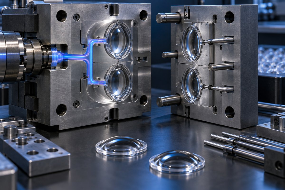
The gate controls how material enters and fills the cavity. Its position affects weld lines, orientation, packing and the location of the gate vestige. A gate placed near a critical optical surface can create unacceptable stress or cosmetic defects, while a long or unbalanced flow path can make replication harder to control.
- Keep the gate vestige outside the clear aperture and functional sealing areas.
- Review flow length and thickness transitions before freezing geometry.
- Consider how multi-cavity balance will be measured and maintained.
- Document acceptable gate-removal appearance and dimensions.
Venting for Stable Filling
Trapped air can contribute to burns, incomplete filling and deposits. Vent locations should reflect the predicted end-of-fill areas and the material’s processing behavior. Vent depth and maintenance access require control because an effective vent must release gas without creating flash.
Cooling and Thermal Balance
Optical surfaces and thick sections can retain heat differently. Uneven cooling may create warpage, sink or cycle-to-cycle variation. Cooling design should support uniform temperature around the cavity and inserts while allowing practical maintenance. The process window should be evaluated with the actual resin grade.
Ejection Without Optical Damage
Ejection forces must act on robust, non-optical areas. Ejector marks, drag and deformation are common risks when the part has insufficient draft or delicate features. Review parting lines, draft, undercuts and release direction together with the assembly design.
Optical Inserts and Datum Strategy
Precision optical inserts need repeatable location, support and orientation in the mold base. The datum scheme should connect the optical surface to the molded mechanical features. Insert serviceability also matters: production teams need a controlled method for cleaning, removal, replacement and requalification.
Questions to Resolve Before Tool Release
| Area | Release question |
|---|---|
| Optics | Where are the clear aperture and critical optical datums? |
| Flow | Where will gates, weld lines and the end of fill occur? |
| Surface | Which zones have cosmetic or coating requirements? |
| Assembly | Which features locate the part and control optical alignment? |
| Validation | How will first articles and production samples be inspected? |
Use DFM Before Cutting Steel
A focused DFM review can identify changes to wall thickness, ribs, flanges, draft and tolerance allocation while they are still inexpensive. It also aligns the tool design with the intended molding and inspection process. Learn more about high-precision optical injection molds and precision optical molding.
Frequently Asked Questions
Can the gate be placed on an optical surface?
It is generally preferable to keep gate vestige and high-stress flow effects outside the clear aperture. The final decision depends on geometry and functional requirements.
Why does insert maintenance belong in the design review?
Cleaning and replacement can change insert position or surface condition. A planned maintenance and requalification method supports consistent production.
When should mold flow analysis be considered?
It is useful when geometry, material, cavity balance or optical stress makes the fill pattern difficult to predict from experience alone.
Contactez Silver Optics to review your optical part, target resin, quantity and tooling requirements.
Vous aimerez peut-être aussi


Services & Capacités
Ressources
Obtenez un devis gratuit
Copier©2025 | Silveroptics. | Tous droits réservés
Service
Response Time: Within 24 Hours
